
Static routing adalah metode konfigurasi routing yang digunakan untuk menentukan jalur yang digunakan oleh router untuk mengirimkan paket.
Dalam static routing, kita secara manual menentukan jalur yang digunakan oleh router untuk mengirimkan paket. Jika ada perubahan topologi jaringan atau perubahan lainnya, kita harus secara manual mengupdate konfigurasi routing.
Static routing digunakan dalam jaringan yang tidak terlalu kompleks atau jaringan yang tidak memerlukan perubahan routing yang sering. Namun, dalam jaringan yang lebih besar atau jaringan yang memerlukan perubahan routing yang sering, dynamic routing digunakan sebagai pilihan yang lebih baik.
Pada artikel ini kita akan mengulas bagaimana konfigurasi static routing di Cisco Packet Tracer. Mari simak langkah-langkahnya bersama.
Topologi Jaringan
Kita memiliki perangkat 3 Router, 3 Switch dan 5 PC dan akan kita setting static routing.
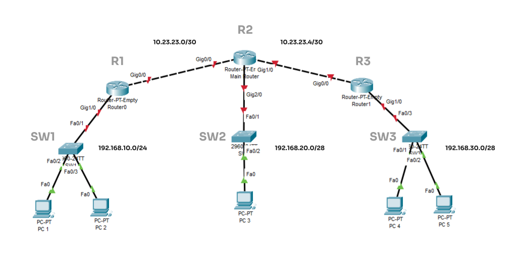
Gambar 1. Topologi Jaringan
Kita akan membagi konfigurasi menjadi 3 bagian, yaitu sebagai berikut.
1. Konfigurasi IP address PC
Berdasarkan topologi yang tertera pada Gambar 1. Maka kita akan konfigurasi IP address setiap PC sebagai berikut.
| PC 1 | PC 2 | PC 3 | PC 4 | PC 5 | |
|---|---|---|---|---|---|
| IP Address | 192.168.10.2 | 192.168.10.3 | 192.168.20.2 | 192.168.30.2 | 192.168.30.3 |
| Netmask | 255.255.255.0 | 255.255.255.0 | 255.255.255.240 | 255.255.255.240 | 255.255.255.240 |
| Gateway | 192.168.10.1 | 192.168.10.1 | 192.168.20.1 | 192.168.30.1 | 192.168.30.1 |
Tabel 1. Alokasi IP Address untuk setiap PC
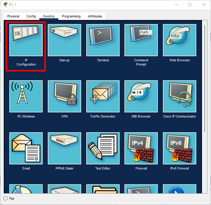
Untuk melakukan setting IP Address pada setiap PC. Silakan klik PC, kemudian menu Desktop, pilih IP Configuration.
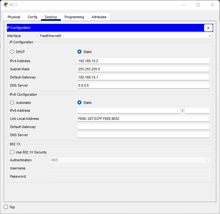
Lakukan setting IP address ke setiap PC sesuai dengan alokasi IP address pada Tabel 1.
2. Konfigurasi IP address Router
Berikut alokasi IP address untuk setiap interface pada router.
| R1 | Port G0/0 | Port G1/0 |
|---|---|---|
| IP Address | 10.23.23.1 | 192.168.10.1 |
| Netmask | 255.255.255.252 | 255.255.255.0 |
Tabel 2. Alokasi IP Address Router 1
| R2 | Port G0/0 | Port G1/0 |
|---|---|---|
| IP Address | 10.23.23.2 | 10.23.23.5 |
| Netmask | 255.255.255.252 | 255.255.255.252 |
Tabel 3. Alokasi IP Address Router 2
| R3 | Port G0/0 | Port G1/0 |
|---|---|---|
| IP Address | 10.23.23.6 | 192.168.30.1 |
| Netmask | 255.255.255.252 | 255.255.255.240 |
Tabel 4. Alokasi IP Address Router 3
Selanjutnya mengetahui alokasi IP address setiap interface pada semua Router. Mari kita mulai konfigurasi IP Address pada Router.
Untuk melakukan konfigurasi router melalui CLI (Command Line Interface), klik pada Router kemudian klik menu CLI.
Konfigurasi IP address R1
R1>enable
R1#configure terminal
Enter configuration commands, one per line. End with CNTL/Z.
R1(config)#interface g1/0
R1(config-if)#ip address 192.168.10.1 255.255.255.0
R1(config-if)#no shutdown
R1(config-if)#
%LINK-5-CHANGED: Interface GigabitEthernet1/0, changed state to up
%LINEPROTO-5-UPDOWN: Line protocol on Interface GigabitEthernet1/0, changed state to up
R1(config-if)#interface g0/0
R1(config-if)#ip address 10.23.23.1 255.255.255.252
R1(config-if)#no shutdown
R1(config-if)#
%LINK-5-CHANGED: Interface GigabitEthernet0/0, changed state to up
Command atau perintah yang diketikan di terminal CLI hanya yang ditandai huruf tebal.
Konfigurasi IP address R2
R2>enable
R2#configure terminal
Enter configuration commands, one per line. End with CNTL/Z.
R2(config)#interface g0/0
R2(config-if)#ip address 10.23.23.2 255.255.255.252
R2(config-if)#no shutdown
R2(config-if)#
%LINK-5-CHANGED: Interface GigabitEthernet0/0, changed state to up
%LINEPROTO-5-UPDOWN: Line protocol on Interface GigabitEthernet0/0, changed state to up
R2(config-if)#interface g1/0
R2(config-if)#ip address 10.23.23.5 255.255.255.252
R2(config-if)#no shutdown
R2(config-if)#
%LINK-5-CHANGED: Interface GigabitEthernet1/0, changed state to up
%LINEPROTO-5-UPDOWN: Line protocol on Interface GigabitEthernet1/0, changed state to up
R2(config-if)#interface g2/0
R2(config-if)#ip address 192.168.20.1 255.255.255.240
R2(config-if)#no shutdown
R2(config-if)#
%LINK-5-CHANGED: Interface GigabitEthernet2/0, changed state to up
%LINEPROTO-5-UPDOWN: Line protocol on Interface GigabitEthernet2/0, changed state to up
Command atau perintah yang diketikan di terminal CLI hanya yang ditandai huruf tebal.
Konfigurasi IP address R3
R3>enable
R3#configure terminal
Enter configuration commands, one per line. End with CNTL/Z.
R3(config)#interface g0/0
R3(config-if)#ip address 10.23.23.6 255.255.255.252
R3(config-if)#no shutdown
R3(config-if)#
%LINK-5-CHANGED: Interface GigabitEthernet0/0, changed state to up
%LINEPROTO-5-UPDOWN: Line protocol on Interface GigabitEthernet0/0, changed state to up
R3(config-if)#interface g1/0
R3(config-if)#ip address 192.168.30.1 255.255.255.240
R3(config-if)#no shutdown
R3(config-if)#
%LINK-5-CHANGED: Interface GigabitEthernet1/0, changed state to up
%LINEPROTO-5-UPDOWN: Line protocol on Interface GigabitEthernet1/0, changed state to up
Command atau perintah yang diketikan di terminal CLI hanya yang ditandai huruf tebal.
Kita telah selesai melakukan konfigurasi IP address pada setiap interface pada R1, R2, dan R3. Selanjutnya kita akan setting Routing Static.
3. Konfigurasi Static Routing Router
Berikut langkah-langkah untuk konfigurasi Static Routing di setiap router.
Konfigurasi R1
Berikut network dan nexthop yang akan kita tambahkan pada static routing di R1.
| Remote Network | Netmask | Nexthop |
|---|---|---|
| 192.168.20.0 | 255.255.255.240 | 10.23.23.2 |
| 192.168.30.0 | 255.255.255.240/td> | 10.23.23.2 |
| 10.23.23.4 | 255.255.255.252 | 10.23.23.2 |
R1#configure terminal
Enter configuration commands, one per line. End with CNTL/Z.
R1(config)#ip route 192.168.20.0 255.255.255.240 10.23.23.2
R1(config)#ip route 192.168.30.0 255.255.255.240 10.23.23.2
R1(config)#ip route 10.23.23.4 255.255.255.252 10.23.23.2
Command atau perintah yang diketikan di terminal CLI hanya yang ditandai huruf tebal.
Konfigurasi R2
Berikut network dan nexthop yang akan kita tambahkan pada static routing di R2.
| Remote Network | Netmask | Nexthop |
|---|---|---|
| 192.168.10.0/24 | 255.255.255.0 | 10.23.23.1 |
| 192.168.30.0/24 | 255.255.255.0 | 10.23.23.6 |
R2#configure terminal
Enter configuration commands, one per line. End with CNTL/Z.
R2(config)#ip route 192.168.10.0 255.255.255.0 10.23.23.1
R2(config)#ip route 192.168.30.0 255.255.255.240 10.23.23.6
R2(config)#do write
Building configuration…
[OK]
Command atau perintah yang diketikan di terminal CLI hanya yang ditandai huruf tebal.
Konfigurasi R2
Berikut network dan nexthop yang akan kita tambahkan pada static routing di R2.
| Remote Network | Netmask | Nexthop |
|---|---|---|
| 192.168.10.0 | 255.255.255.0 | 10.23.23.5 |
| 192.168.20.0 | 255.255.255.240 | 10.23.23.5 |
| 10.23.23.0 | 255.255.255.252 | 10.23.23.5 |
R3#configure terminal
Enter configuration commands, one per line. End with CNTL/Z.
R3(config)#ip route 192.168.10.0 255.255.255.0 10.23.23.5
R3(config)#ip route 192.168.20.0 255.255.240 10.23.23.5
R3(config)#do write
Building configuration…
[OK]
Command atau perintah yang diketikan di terminal CLI hanya yang ditandai huruf tebal.
Pengetesan Koneksi
Kita telah selesai menambahkan static routing pada setiap router. Selanjutnya kita lakukan pengetesan koneksi antar PC menggunakan Ping.
Klik pada PC 1, kemudian pilih Desktop, dan pilih Command Prompt.
Setelah tampil Command Prompt, lakukan ping ke setiap PC.
Ping PC-1 ke PC-3
Pinging 192.168.20.2 with 32 bytes of data:
Reply from 192.168.20.2: bytes=32 time<1ms TTL=126
Reply from 192.168.20.2: bytes=32 time=1ms TTL=126
Reply from 192.168.20.2: bytes=32 time=10ms TTL=126
Reply from 192.168.20.2: bytes=32 time=1ms TTL=126
Ping statistics for 192.168.20.2:
Packets: Sent = 4, Received = 4, Lost = 0 (0% loss),
Approximate round trip times in milli-seconds:
Minimum = 0ms, Maximum = 10ms, Average = 3ms
Ping PC-1 ke PC-4
C:>ping 192.168.30.2
Pinging 192.168.30.2 with 32 bytes of data:
Reply from 192.168.30.2: bytes=32 time<1ms TTL=125
Reply from 192.168.30.2: bytes=32 time=11ms TTL=125
Reply from 192.168.30.2: bytes=32 time=1ms TTL=125
Reply from 192.168.30.2: bytes=32 time=11ms TTL=125
Ping statistics for 192.168.30.2:
Packets: Sent = 4, Received = 4, Lost = 0 (0% loss),
Approximate round trip times in milli-seconds:
Minimum = 0ms, Maximum = 11ms, Average = 5ms
Ping PC-1 ke PC-5
C:>ping 192.168.30.3
Pinging 192.168.30.3 with 32 bytes of data:
Reply from 192.168.30.3: bytes=32 time<1ms TTL=125
Reply from 192.168.30.3: bytes=32 time=12ms TTL=125
Reply from 192.168.30.3: bytes=32 time=1ms TTL=125
Reply from 192.168.30.3: bytes=32 time=11ms TTL=125
Ping statistics for 192.168.30.2:
Packets: Sent = 4, Received = 4, Lost = 0 (0% loss),
Approximate round trip times in milli-seconds:
Minimum = 0ms, Maximum = 11ms, Average = 5ms
Kita bisa melalukan pengecekan jalur mana saja yang dilewati PC-1 menuju PC-4 atau PC-5 dengan perintah tracert di Command Prompt. Berikut hasil tracert dari PC-1 ke PC-4
Tracing route to 192.168.30.2 over a maximum of 30 hops:
1 0 ms 0 ms 0 ms 192.168.10.1
2 1 ms 0 ms 1 ms 10.23.23.2
3 1 ms 1 ms 11 ms 10.23.23.6
4 14 ms 11 ms 21 ms 192.168.30.2
Trace complete.
Terlihat pada hasil tracert diatas, ketika PC-1 mengirim packet menuju PC-4, data melewati 4 hops. Dimana hop pertama merupakan gateway PC-1 (interface R1), kemudian hop kedua merupakan IP address interface G0/0/0 R2. Hop ketiga merupakan IP address interface G0/0 R3.
Demikian artikel mengenai konfigurasi static routing di Cisco Packet Tracer. Semoga dapat dimengerti dan bermanfaat.